- Welcome to Accuthermo Technology Corp.
- A Total Thermal Solution Provider
Part Number
Rating
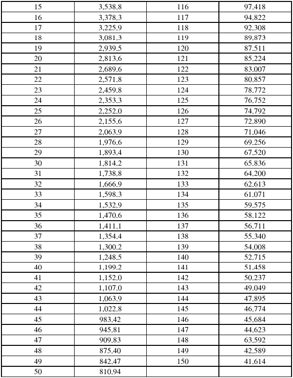
3-1) Rated zero-power resistance R25 : 2.252 KΩ NOMINAL
3-2) B value. B25/85 : 3,977 K ± 1 %
*The B value is calculated using the zero-power resistance values measured at 25 °C and 85°C.
3-3) Temperature coefficient @25°C : -4.4 %/°C
3-4) Dissipation factor. : Approx. 0.5 mW/°C (in air)
3-5) Thermal time constant. : Approx. 0.4 s (in air)
3-6) Toleauce range (tolerance) : 0°C to 70°C (±0.1°C)
3-7) Maximum operating temperature : 150 °C
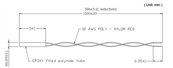
Dimension (mm)
Insulation
between epoxy resin and soldered terminals
5-1 Dielectric withstanding voltage : AC 100V for one second.
5-2 Insulation resistance : Above 100 MΩ at DC 500V.
Climate Tests
6-1) Dry Heat
After the test samples were exposed in air at 100°C for 1,000 hours, the change ratio of the rated zero-power resistance shall be within ±1% of the initial value.
6-2) Damp heat
After the test samples were exposed in the humidity of 95% at 40°C for 1,000 hours,the change ratio of the rated zero-power resistance shall be within ±1% of the initial value.
6-3) Cold
After the test samples were exposed in air at 0°C for 1,000 hours, the change ratio of the rated zero-power resistance shall be within ±1% of the initial value.
6-4) Humidity load
After DC 1mA current was applied to the test samples in the temperature of 40°C and the humidity of 95% for 1,000 hours, the change ratio of the rated zero-power resistance shall be within ±1% of the initial value.
6-5) Change of temperature
One cycle of the change of temperature shall be carried our in the order of the following conditions.
Room ambient temperature.(Initial value)
At -30°C, for 30 minutes.
Room ambient temperature, for 3 minutes.
At + 80°C, for 30 minutes.
Room ambient temperature, for 3 minutes.
After 100 cycles of change of temperature, the change ratio of the rated zero-power resistance shall be within ±1% of the initial value.
Mechanical Characteristics:
7-1) Robustness of terminations
* Tensile to horizontal direction
Hold the thermistor body so that lead wire shall be horizontal. After 1 kg loading weight was applied to the lead wire horizontally for 10 seconds, there shall be no visible damage.
7-2) Free fall
After three times natural fall to a maple board from 75cm high, there shall be no visible damage.
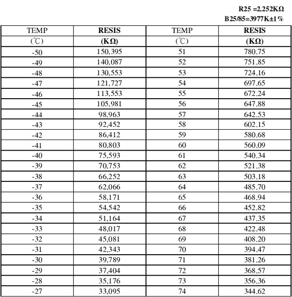
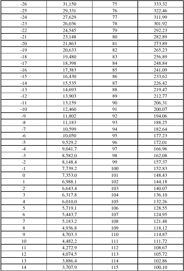
R-T Characteristics
Download
TR2252 Spec AT102011
|


.png)
.png)
.png)
.png)


